I know I’ve gone dark for quite a while, but I am back in a big way! As some people may know, I quit my job back in October of 2023 to pursue some ventures, and now I’m finally able to present this project to the world!

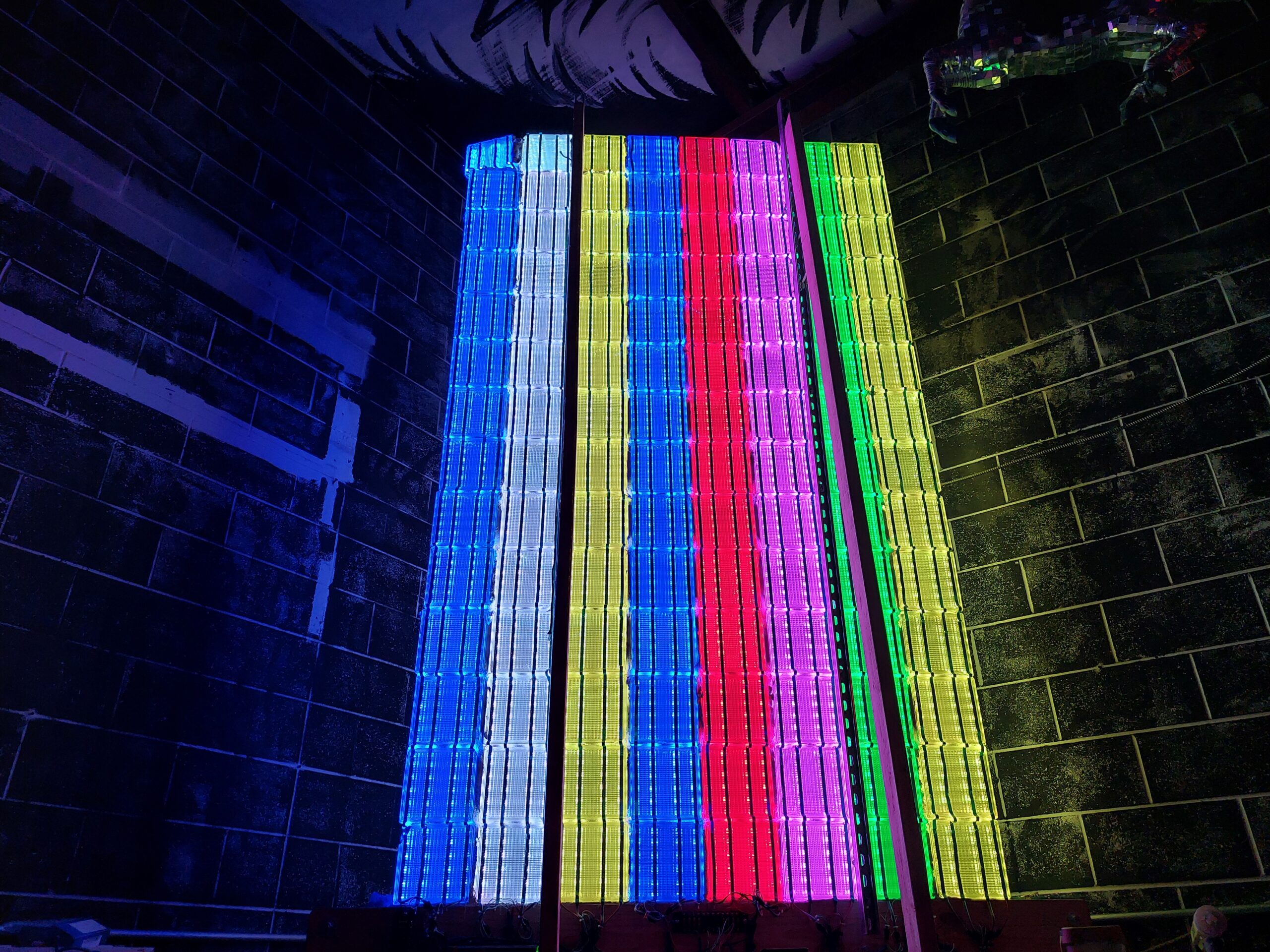
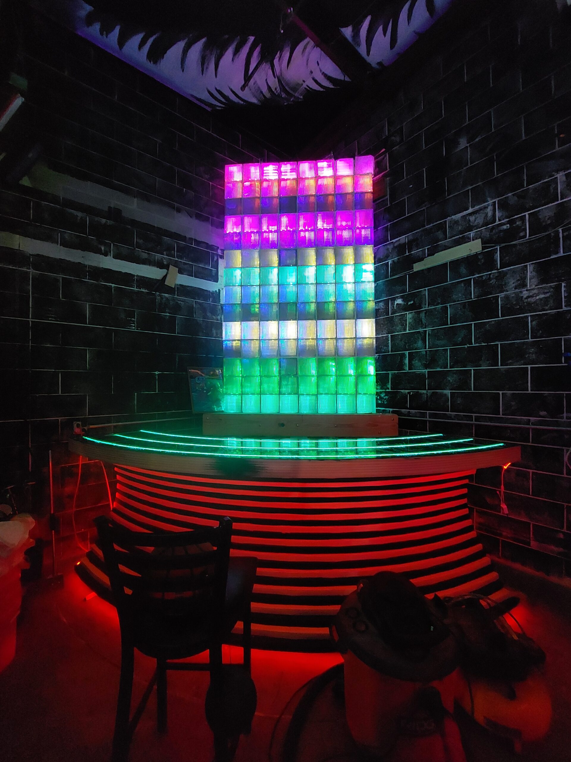
This project is BoneBlocker, a giant, 8×14 glass block wall backlit by over 3.000 addressable LEDs! It’s the backdrop to the Coin-Op’s bar, and they recently reopened as a part of Boneyard Chattanooga!
For those of you unfamiliar with Coin-Op, it’s the brainchild of Brian Hennen, and was a staple of Chattanooga for years! It’s our friendly neighborhood barcade, where you can come in, enjoy a cheap beer or soda, and throw a few quarters at an afternoon of pinball, Puzzle Bobble, or any number of classic arcade games. Since they closed their original location a few years back, many people have expressed just how much they missed the space, and their return is exciting for so many of us!
Back in August, my best friend and co-founder of Boneyard, Lewis Armistead, called me one afternoon while he and Brian were brainstorming. He let me know that “Coin-Op is going to be reopened inside Boneyard, and they were thinking of building a giant, glass block wall behind the bar” and I said, “And you want to make it a giant, playable Tetris-style game!” We were 100% on the same page, but I had no idea how I was going to pull this off. My 9-5 was taking everything from me, and I couldn’t get over to Boneyard while they weren’t open to work on the game.
Thankfully, my wonderful girlfriend Caroline decided to support me, so I could pursue a few projects! With her support, I was able to put in my 2-weeks, and start working!
Lewis and Brian got to work constructing the wall while I took a sample of the blocks they acquired and ran a test. I ordered a very dense roll of WS2812B LEDs from BTF-LIGHTING, and they were intensely bright! The colors were vibrant, and I couldn’t wait to see the whole wall lit up!
After some testing, I was really happy with the outcome and how I could control the LEDs with my Arduino Mega and the FastLED library. I ran the numbers, and with the original density of 60 LEDs/Meter, we were going to be around 1500 watts of power draw just for the wall. That’s pretty much an entire residential circuit, so I decided on going with 30 LEDs/Meter, which still provided great results. I tested this by activating only every-other LED on the test block, and we were all pretty happy with how it looked.
While Brian and Lewis finished up the wall, I sourced the LEDs straight from BTF-Lighting on Alibaba. Their turnaround was fantastic, and I don’t believe we found a defective strip or even a dead LED in the massive order! I waited until they had finished the wall, and then got to work stringing the LEDs. I decided on 4 strips per column run vertically with 6 LEDs per strip per block row. Each LED strip would be driven on its own channel, and there would be an unused LED between each row for 97 LEDs per strip and 24 LEDs per block!
Since the wall was to be placed in the corner of the room, Lewis had the brilliant idea to build the base on casters. That way, it could be pulled away from the wall and rotated to a position where a ladder could be placed for working on it. Moving the completed wall is nerve-wracking, but the structure is built extremely well, and while stationary, it is anchored to the building’s walls. Hopefully, we won’t need to pull it away again for a very long time!
The wall oriented for LED installation.
To attach the LEDs to the wall, I considered epoxy, tape, and a few other options. Ultimately, I decided on hot glue (and lots of it). I thought this process would go a little faster than it did, but I made the mistake of doing each strip individually. The time up and down the ladder is what really kills your productivity. After having done 4 of the 8 columns, I decided to do the remaining 4 all together, and progress was much faster. I left the LEDs spooled up, and allowed them to unspool as I worked from the bottom up to attach them.
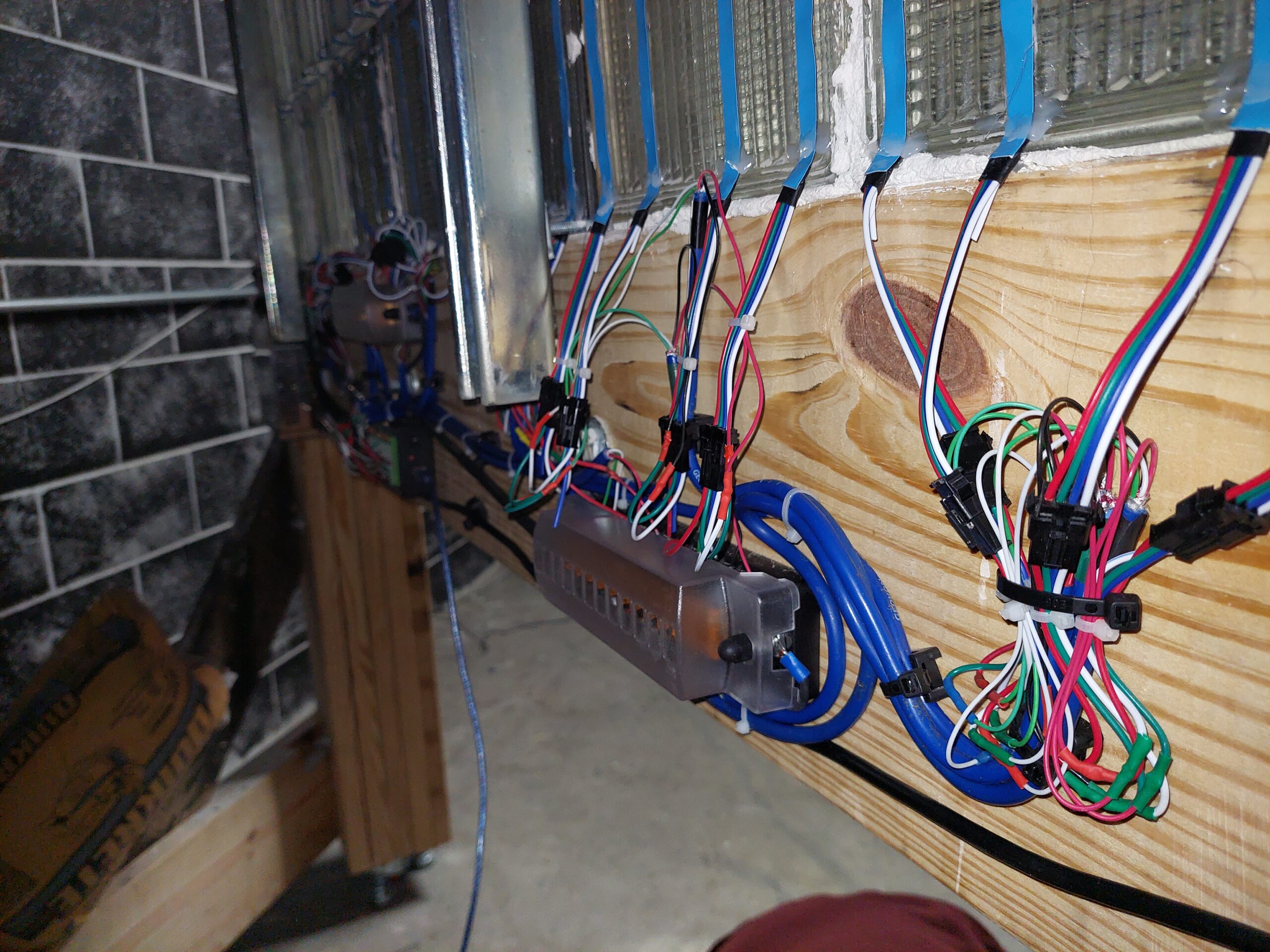
Once the LEDs were strung, I got to work wiring them. I wanted to ensure each strip was individually fused to make a fault less likely to take out the whole wall. This has the added benefit of making diagnostics easier. I had a few friends provide me with some nice scrap wire from industrial sensor installations (too short to be used for their applications), and I set to work creating what I hope will prove to be a serviceable backbone.


After wiring the columns, I couldn’t help but get excited! I used the same code on the Arduino Mega to control each column individually just by holding their data connections to the one output pin until the LEDs were a solid color. And WOW! The wall lit up beautifully!
Now it was time to start programming! But I ran into a little problem… My plan had been to use the same Arduino Mega to drive the entire wall with the FastLED library. There’s enough IO to drive all 32 strips, so I did not think this would be a problem, but upon starting to write the code, the Arduino IDE informed me that I was out of RAM after initializing all 32 outputs. I could only control a little over half the wall with one Arduino Mega. “No problem,” I thought, “I can just use 2”. But man, am I glad I stopped to do some back-of-the-napkin math! I realized that, using an Arduino’s USB to serial connection, I was only going to be able to send enough data to update the LEDs at around 3 to 5 times per second at best. And that is a big problem if we wanted to play a game on this thing!
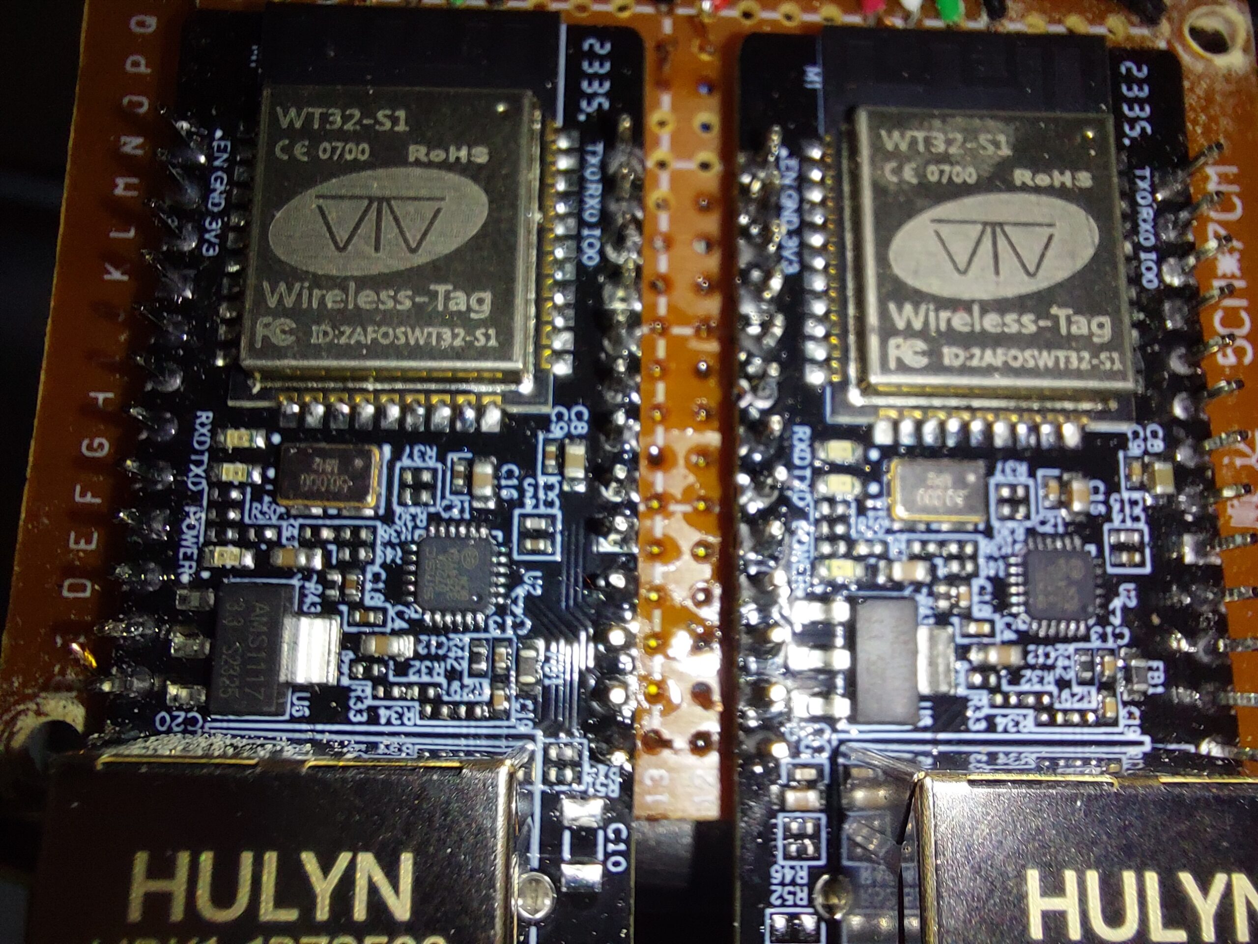
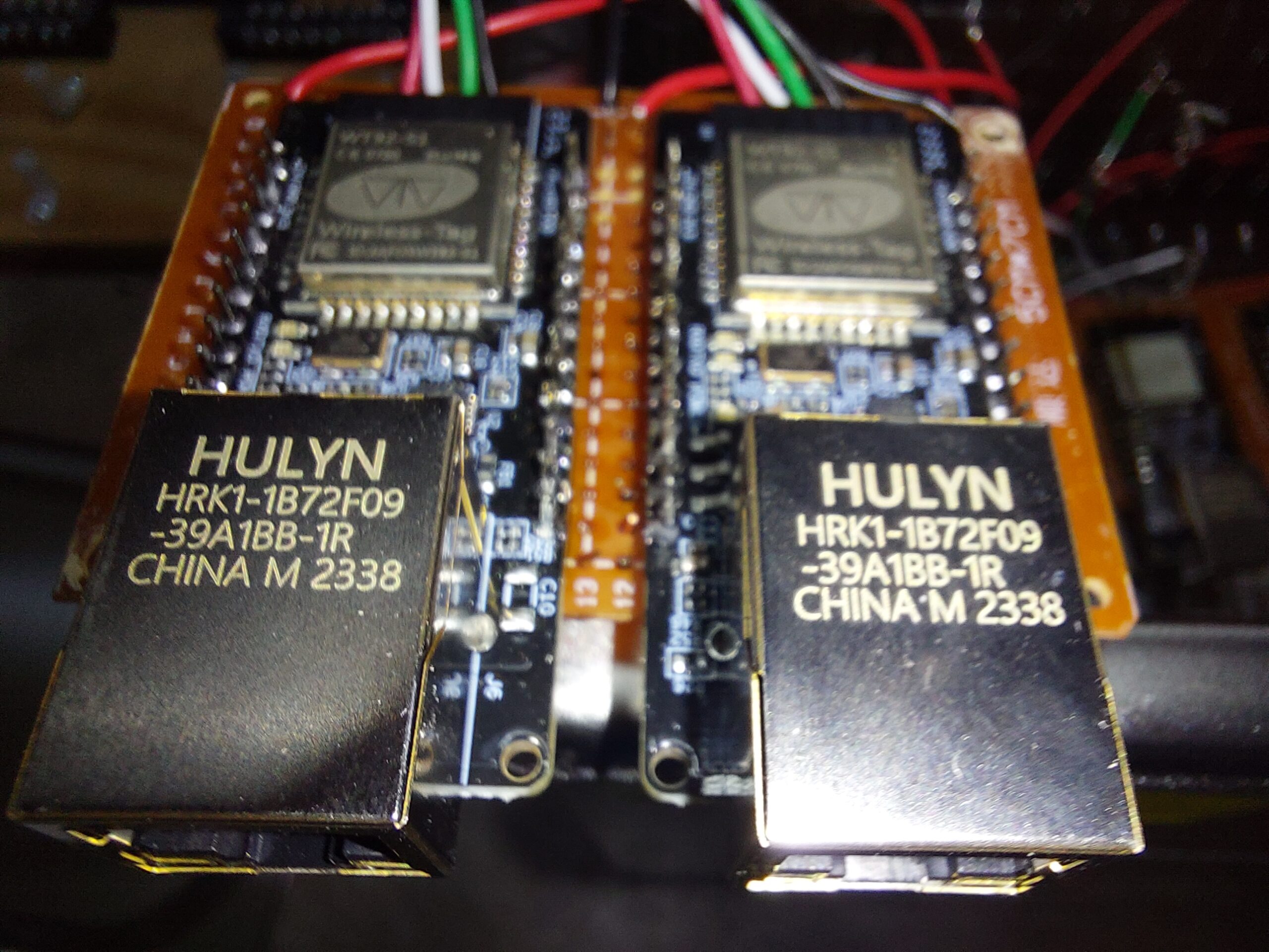
So, I went looking for solutions. After some research, it seems many people have been doing some CRAZY projects using the WLED ESP32 firmware. I wanted to avoid a wireless connection if I could, so I decided on WT32-ETH01 boards. These guys are ESP32 compatible boards with onboard Ethernet and are supported by the WLED web installer! After reading through the WLED documentation on performance, I decided on using 4 outputs per board, and that meant I’d use 1 board per column. In hindsight, this is probably overkill, but the cost overall isn’t too bad to ensure we had enough performance to update the wall very quickly.
ESP32 based boards with WLED installed are fantastic for these kinds of LED projects, but they need some help. The ESP32 provides 3.3V logic outputs, and the LEDs are expecting 5V communication. For many smaller projects, this may not be an issue, but it is recommended to run a logic-level converter to step the 3.3V up to 5V. The larger your installation and the longer your LED strips, the more important it is to use 5V logic to ensure each LED gets its data.
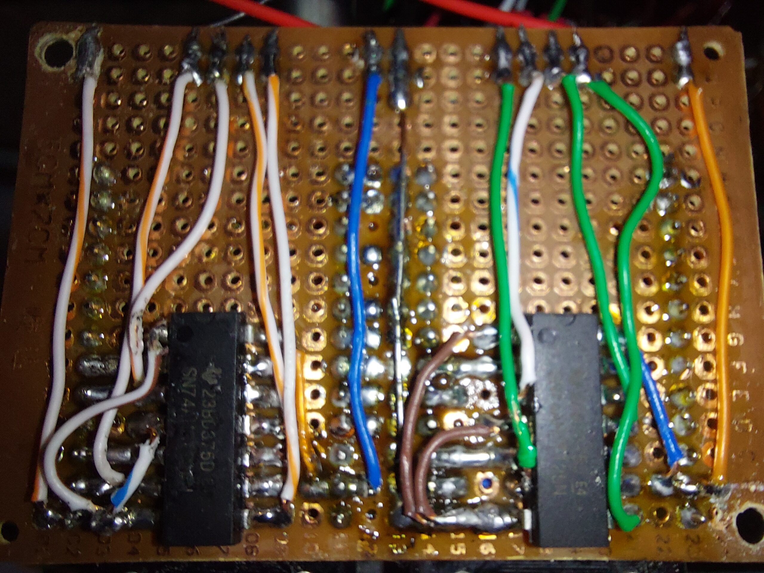
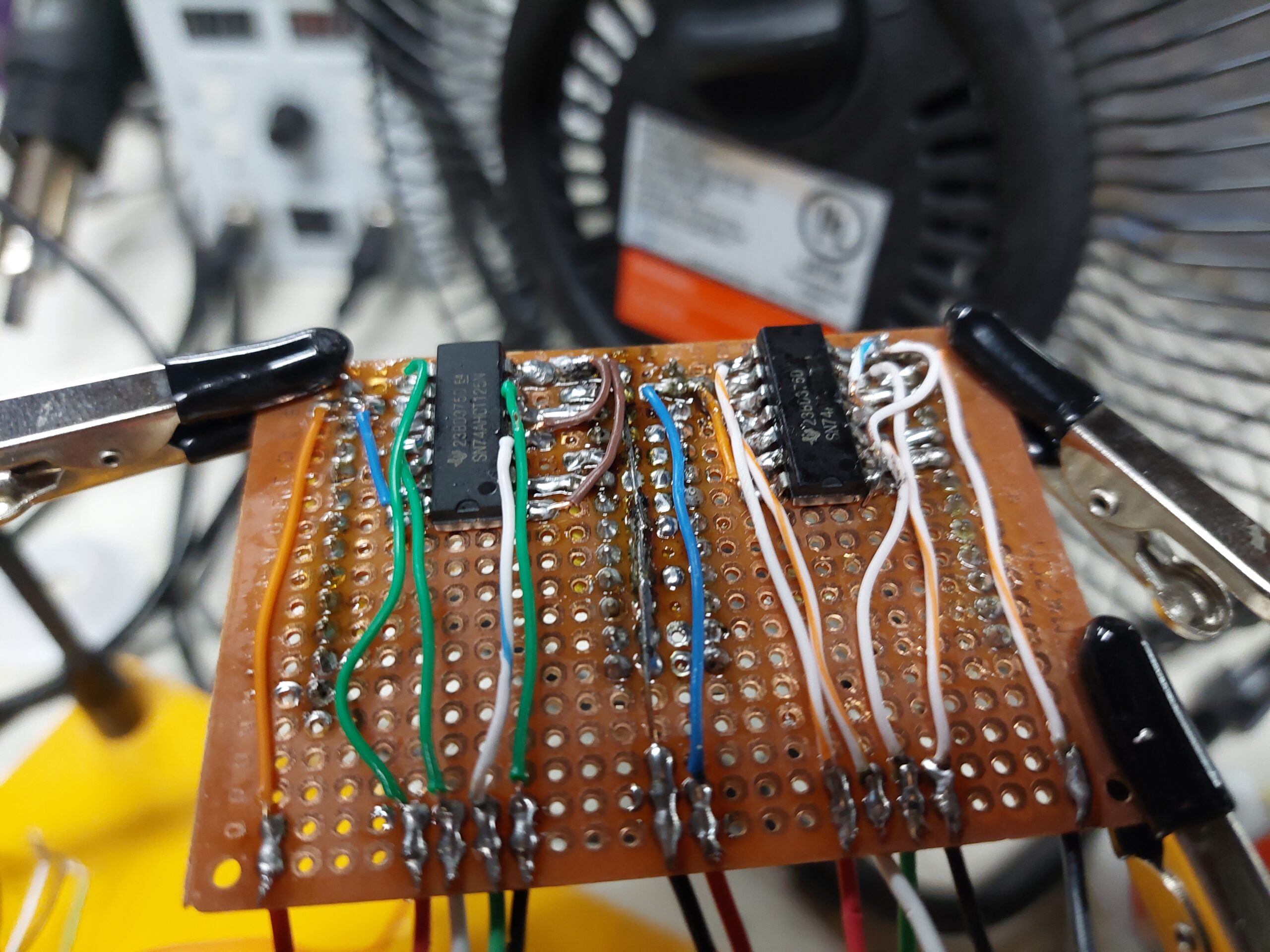
I purchased 2 different logic-level converters, and ultimately decided to use the Texas Instruments SN74AHCT125N. This IC comes recommended from the WLED documentation, and Adafruit provides some great documentation and drawings showing how to use it for driving their NeoPixel LED strips (which are very similar to the WS2812B strips I’m using) from a Raspberry Pi (another 3.3V logic device).
I decided to make the boards for the logic-level converters and their connections to the ESP32 modules. This may have been the biggest mistake I made in this whole project. They turned out functional, and I’m proud they are working, but I would have been way better off with a printed circuit board. Stripping and soldering tiny pieces of Ethernet wire as the traces on protoboard is very time consuming, and just one of these boards (there are 4 in total with each housing 2 modules and 2 converters) takes about 6 to 8 hours to complete.
Because I had originally wired the wall for a single Arduino Mega, I wanted to make sure the layout of all these controllers was compact while being accessible. I ended up creating a project panel on a piece of plywood, and it turned out pretty clean!
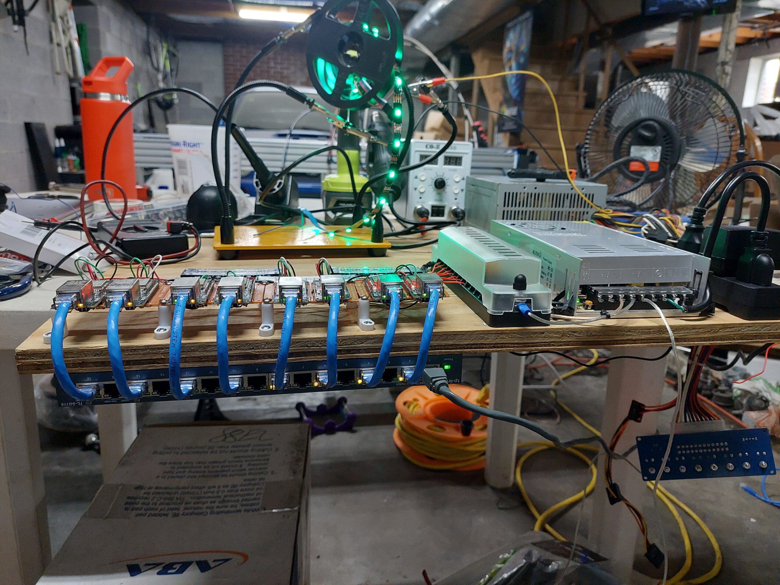
This panel was mounted perpendicular to the wall on the back side with all of the wiring. Around the same time I completed these LED controllers, Lewis and Brian were able to finish building the bar for the space. I think they compliment each other beautifully!
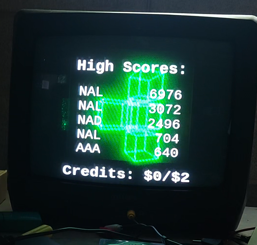
From this stage, it was all about writing the software for the game. I knew that I wanted to build this with Node.js, because I had used that in the past for passing data from serial to a web page. and I was using an Arduino Mega for the controller inputs. I had done some work to make an animation sequence that will play on the upcoming block display. This is my first time doing any software development in 3D rendering, and I chose Three.js to make it happen. I’m very pleased with the outcome! It has just the right kind of retro/arcade vibe I was wanting to achieve!
I worked with John Hugget to develop an “emulator” for the block wall’s layout. This web page was a dynamically configured table with cells representing each block and served as the foundation I used for testing my game logic. I had never written a game before, but every tutorial I found involved writing to the screen. Unfortunately, there is no traditional ” screen” in this case, so I was forced to just start writing what I thought I needed. I looked at the fantastic, open source game BlockRain for inspiration on how to store and render the different shape orientations, but then I kind of just started writing the different functions I thought I needed. Soon enough, I had a playable rendition of the game working in the cells on the webpage. Those were getting updated with data from a multidimensional array that was where the game was actually being played. From there, all I needed was to figure out the WLED API calls I needed to make to update the wall to reflect the table I was playing the game on, and suddenly, the game was working in real-time on the wall!

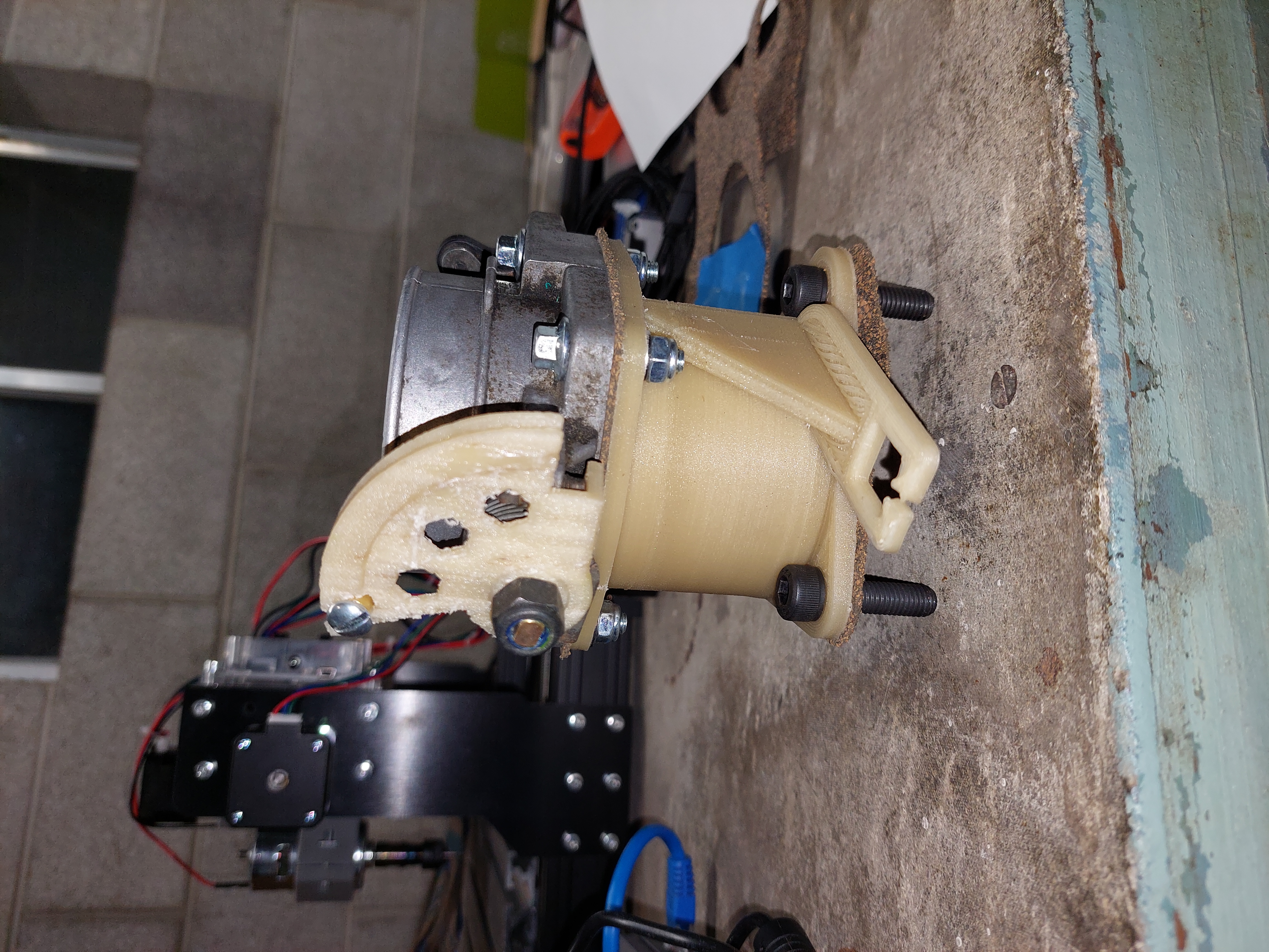
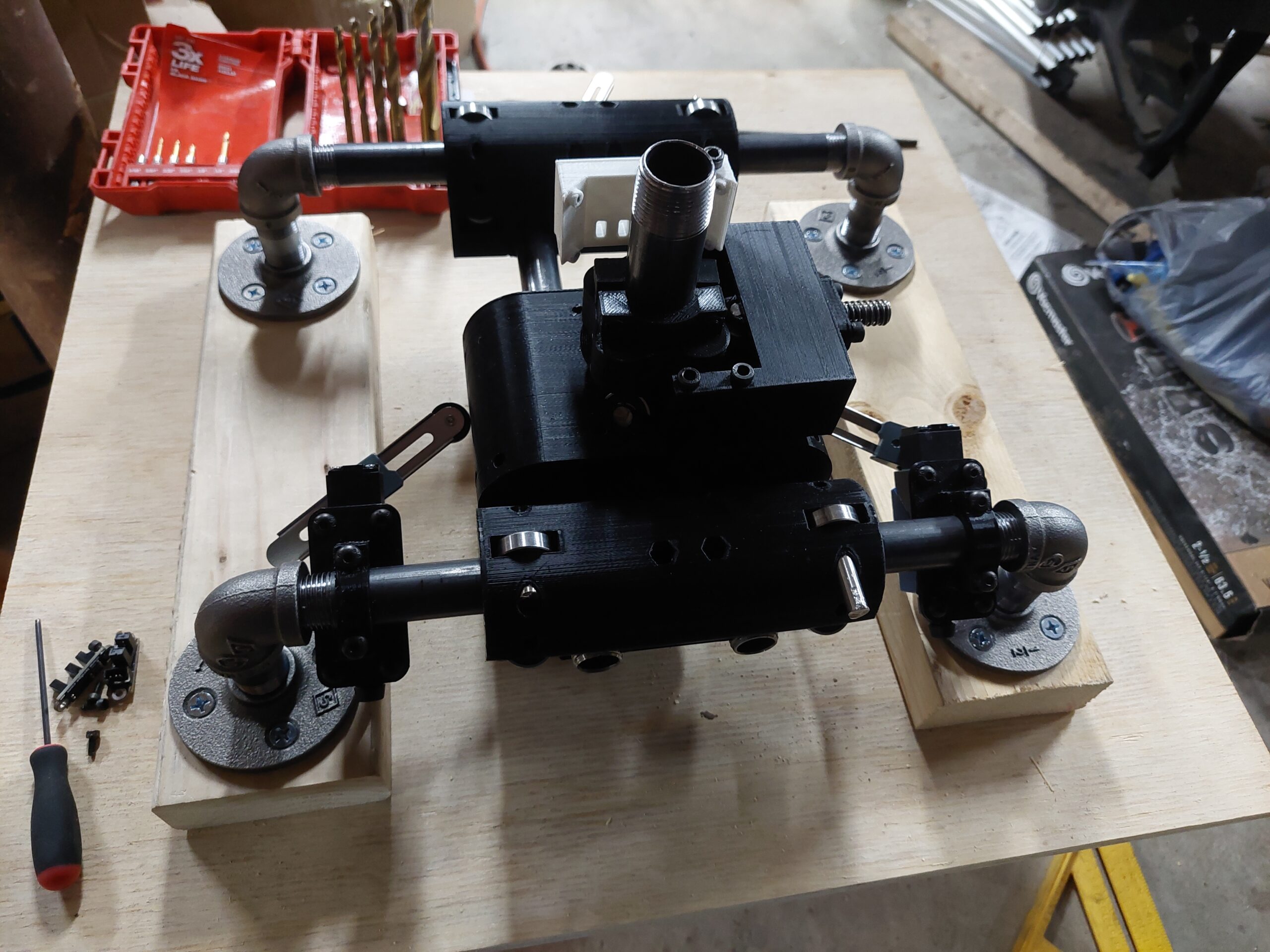
So, then we came to the final steps. I needed to build the controller. Early in the project, we had come up with the idea to make the game playable with a glass block. It was an ambitious goal, but I thought I could pull it off. I decided to make an XY gantry system using skateboard bearings and steel pipe. 3D printing was utilized to make each one of the carriages, and the entire block assembly could be rotated to rotate the shape on the wall. It uses a 4-lobe cam system with a spring-loaded skate bearing to ensure that the block snaps to each quarter-turn.
For holding the block, I reached out to Donald Sayers. I knew he had a Voron 2.4, and I thought he could print me a high quality clear housing for the glass block itself. He took a look at my (admittedly uninspired) design, and asked to take a crack at it. I’m so glad he did! His idea was to emphasize the “chunk” in the design, and it’s almost like you’re holding some sort of caged power in your hands as you play the game. He absolutely nailed it!
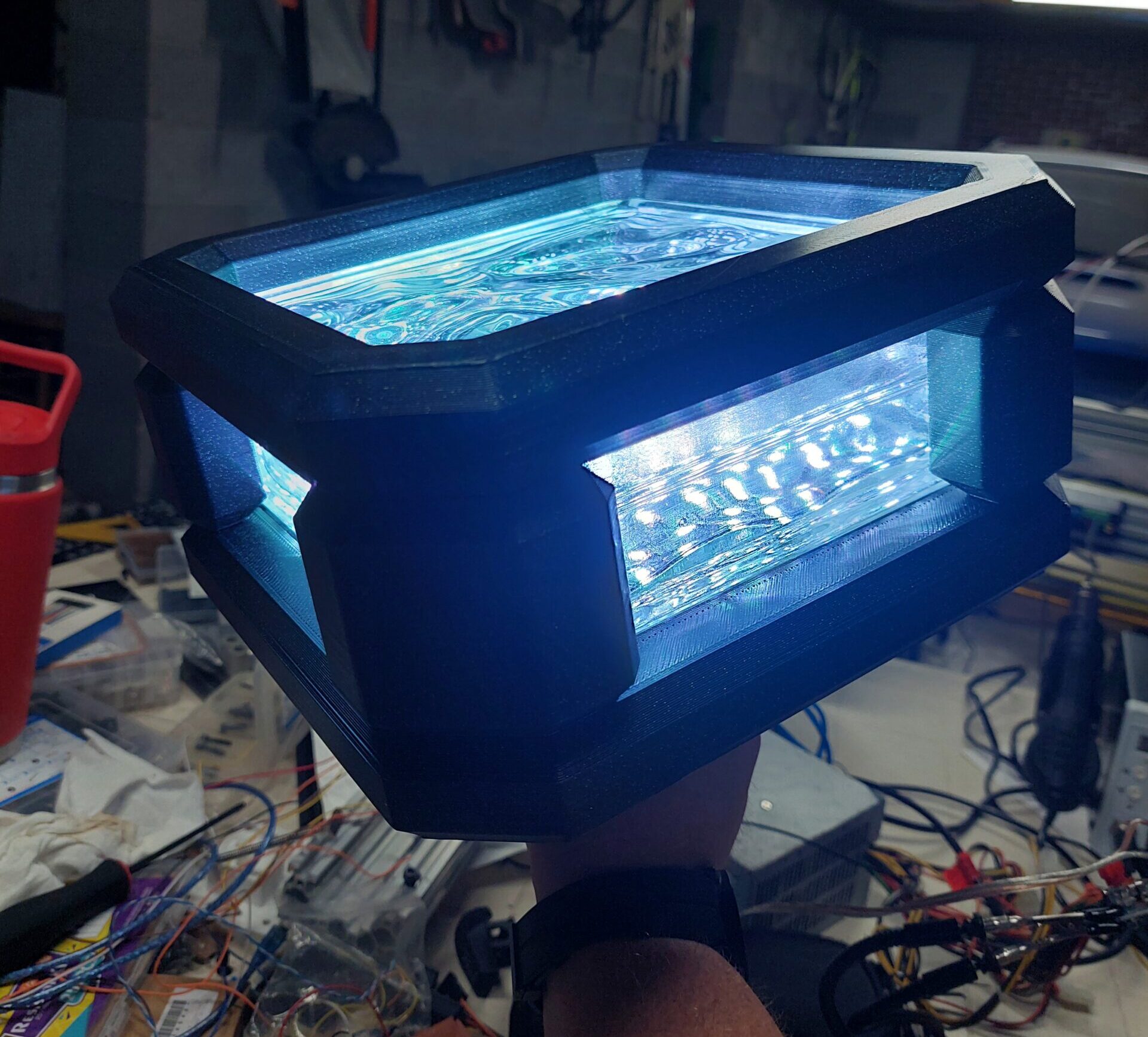
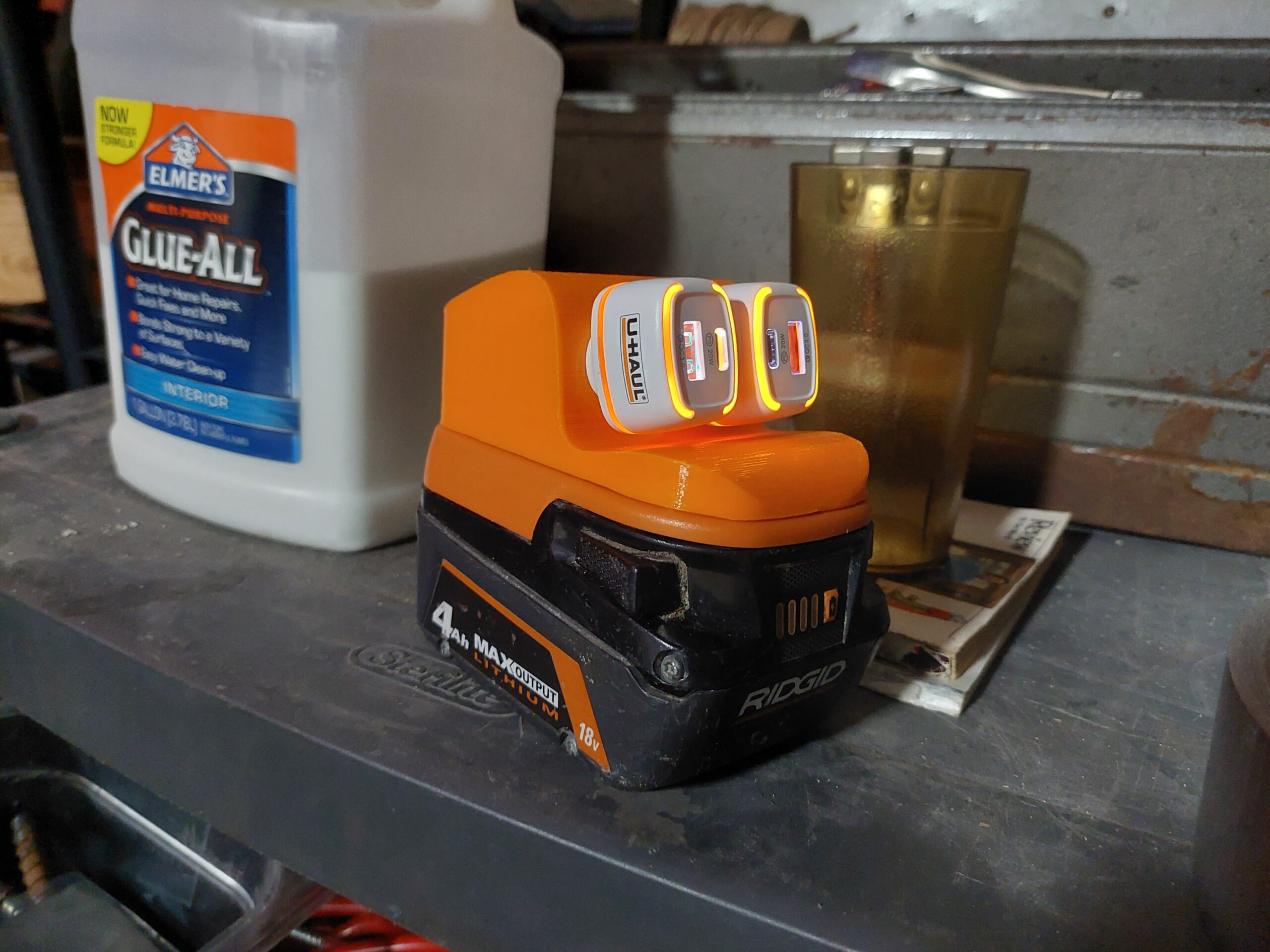
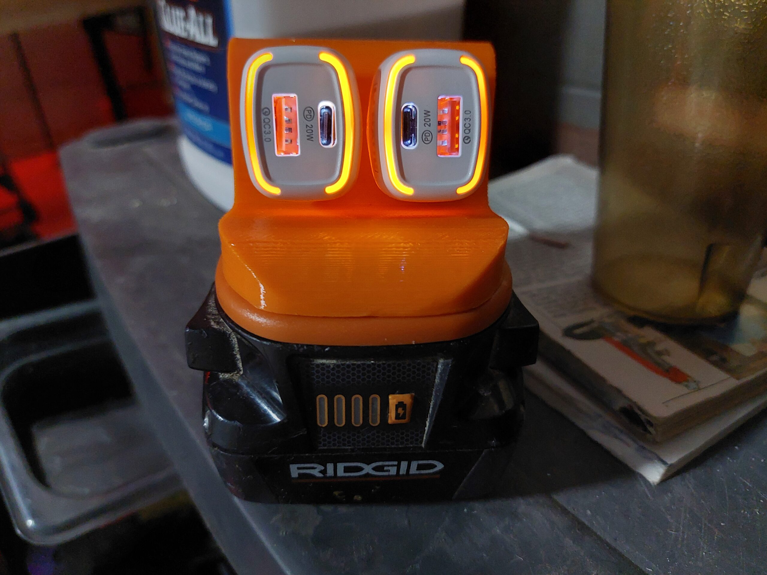
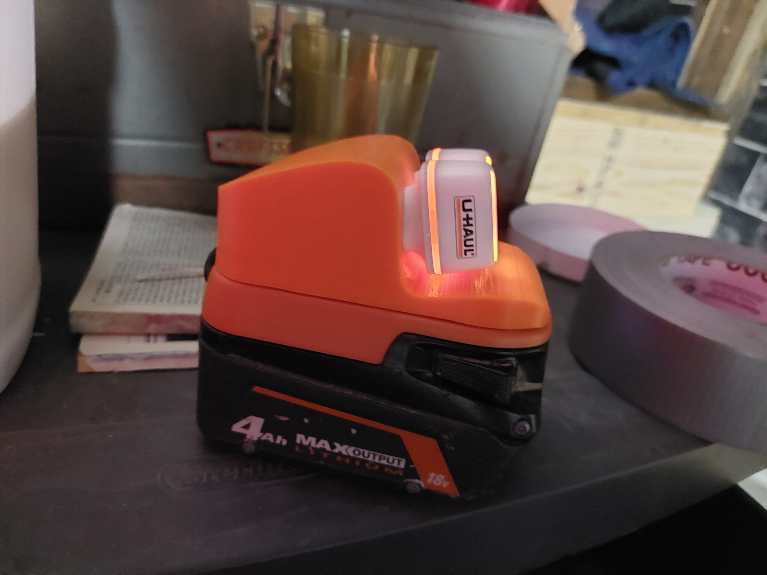
Now, you’ll remember that each block in the wall has 24 LEDs. I wanted to do animations with these LEDs in the controller, so I needed more. In total, this thing ended up with 185 LEDs! Needless to say, they are running at a fraction of their potential brightness. Otherwise, they might blind somebody!
I also wanted the base of the controller to have a steel faceplate. Hopefully with a little bit of patina. Early on, I had picked up a 3/8″ steel plate, and I had my friends Nick and Lucas over at Anval Designs help me plasma cut it. The piece turned out great, and really adds to the industrial vibe of the whole project!
Finally, Lewis and I worked to build a podium and integrate the entire project into the space. The goal was to take up minimal floor and railing space, and I absolutely love the pedestal he came up with! You play the game from an integrated overlook in the space, and I think it adds to the sense of scale you get with the whole project. Especially while you’re watching someone else play!

The final result is very satisfying to play! We’re still buttoning up the physical installation, but it’s currently playable, and hopefully will be finalized in the next few weeks. Check out Boneyard’s Jared Padovani testing out the gameplay!
And finally, I’d like to share one of the wall’s party tricks. It’s able to be sequenced with xLights, so we were able to play this animation for Boneyard’s 2-Year anniversary/Coin-Op’s reopening party.